In this paper, we take the twists drill as an example to introduce the various parts of the twists drill.
Parts of twist drill about cutting angle
Helix angle
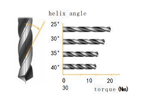
The helix angle is the angle at which the spiral groove of a drill bit is inclined relative to its axial direction. The helix angle on the outer periphery of the drill bit is equal to the lead angle.
In general, the helix angle is typically around 30 degrees. When it’s less than 30 degrees, it’s referred to as a weak helix angle, and when it’s greater than 30 degrees, it’s called a strong helix angle. Drill bits with a weak helix angle have shorter spiral groove lengths, which results in good chip removal performance, but they have a smaller lead angle, leading to increased cutting resistance. On the other hand, drill bits with a strong helix angle have a larger lead angle, which reduces cutting resistance. However, the cutting edge of the drill bit may become more fragile, making it prone to chipping and breakage.

Rake angle
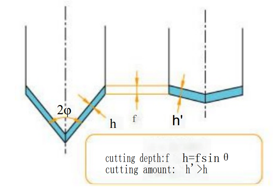
The size of the rake angle affects the thickness of the chips. As seen in the diagram below, with a constant feed rate (f), when the rake angle is small, the depth of cut (h) in the vertical direction is reduced, and when the rake angle is large, the depth of cut (h’) increases, resulting in thicker chips. Consequently, the chip thickness increases.
To prevent chips from wrapping around the drill bit, one method is to increase the rake angle, making the chips more prone to breaking. This effectively solves the problem of chip entanglement.
Relief angle
To avoid hindering the feed motion of the drill bit, a relief angle is provided on the cutting edge behind the main cutting edge. As shown in the diagram below, when the drill bit completes one revolution, the cutting edge advances axially by a distance of “f.” If the relief angle is less than or equal to the angle θ1 formed between the outermost periphery of the drill bit and the feed rate, the rear face of the drill bit will make contact with the workpiece, resulting in a sharp increase in axial force. Therefore, the minimum relief angle must be greater than the value calculated using the formula below. The relief angle is typically set in the range of 7° to 15°. Increasing the relief angle reduces the contact area between the workpiece and the rear face of the drill bit, leading to a decrease in axial force, but it can also make the drill bit more susceptible to chipping and breakage.

Front angle
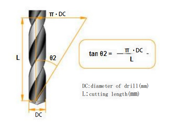
The front angle of a drill bit (in the axial direction) is related to the helix angle. The larger the helix angle, the larger the front angle. The actual front angle is influenced by the position of the cutting edge, and in the outer peripheral part of the drill bit, the helix angle and the front angle are equal.
The front angle θ2 (which is equivalent to the helix angle) on the outer peripheral part of the cutting edge can be calculated using the formula shown in the diagram below.
Parts of twist drill about drill groove
Groove length
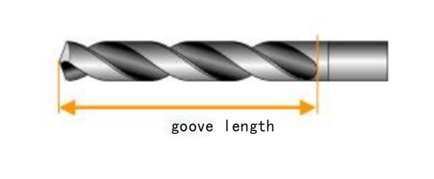
The groove length affects the accuracy of the hole and the lifespan of the drill bit. The groove length is determined by the depth of the hole and the amount of regrinding required. When the groove length increases, the corresponding length of the drill bit also increases, leading to a decrease in the drill bit’s rigidity. Drill bits with lower rigidity tend to experience strong oscillations when entering the workpiece, and their rotational center cannot remain fixed. This reduction in rigidity diminishes the accuracy of the hole and adversely affects the tool’s lifespan. Therefore, it is recommended to choose drill bits with the shortest possible groove length.
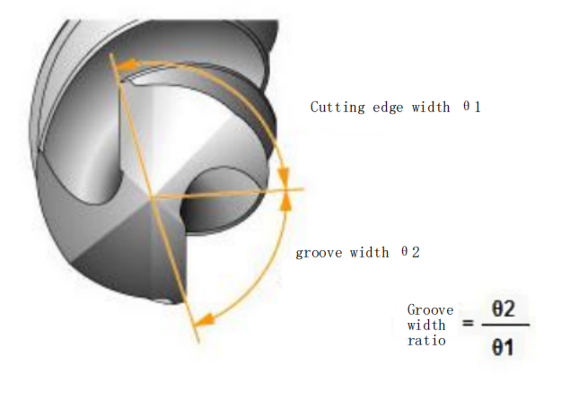
Groove width
The groove width of a drill bit is determined while taking into account the strength of the drill bit and chip handling characteristics. Its balance is expressed as the groove width ratio, which is the ratio between the width of the cutting edge at the top of the drill bit (θ1) and the groove width (θ2). The groove width ratio typically falls in the range of 1 to 1.2. Drill bits that prioritize chip evacuation performance tend to have a larger groove width ratio, while those emphasizing rigidity have a smaller groove width ratio.
Parts of twist drill about drill body
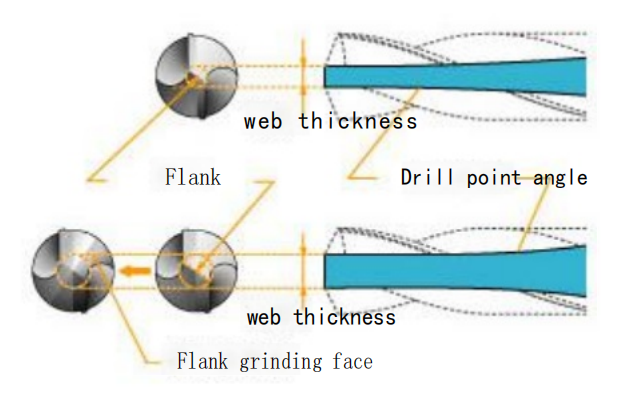
Web thickness
The web thickness, drill point angle, and groove width determine the cross-sectional shape of the drill bit.
For example, in cases of a very thick web, it can increase the rigidity of the drill bit, but it reduces the area of the flutes, making chip evacuation more challenging. Simultaneously, the axial cutting forces increase, which can have an overall impact on the drilling process. In the case of high-speed steel drill bits used on drilling machines, the web thickness is typically around 10% to 20% of the drill bit diameter. For smaller diameter drill bits, this proportion is often larger, and it decreases as the diameter increases. High-speed steel drill bits are known for their toughness, so chip evacuation is a priority.
However, in high-rigidity, high-power machining centers using high-speed, high-efficiency carbide drill bits, the web thickness can be as high as 20% to 30% of the drill bit diameter. This is done to improve the drill bit’s rigidity so that higher feed rates can be achieved and to break the chips into smaller pieces. As the web thickness increases, the length of the top web portion also increases, which results in a larger area for compression, leading to increased axial forces. To reduce axial forces, the top web needs to be ground, and its length needs to be reduced.
Drill point angle, on the other hand, is used in cases where the web thickness is relatively thin, particularly with high-speed steel drill bits or deep-hole drill bits. It can improve the rigidity of the drill bit. Typically, for a 100mm diameter drill bit, the drill point angle should be within 2mm. If the drill point angle is too large, it can make chip evacuation difficult.
Width of cutting edge band
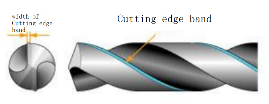
Drill bits possess guidance and friction characteristics, and a suitable range for the width of the cutting edge band is typically around 6% to 10% of the drill bit diameter. When it comes to deep-hole machining, long drill bits have a significant length of contact with the hole’s inner wall, which is why the cutting edge band width is relatively small. This is done to reduce frictional forces.
To improve the roundness and surface roughness of the machined hole, some drill bits have an increased cutting edge band width to enhance the burnishing effect.

Taper
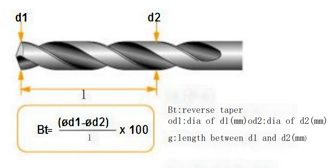
In machining, to reduce friction between the hole wall and the outer periphery of the twist drill bit, a reverse taper or countersink is provided on the outer diameter of the drill bit. The reverse taper is sometimes expressed in terms of an angle, but generally, it is represented by the reduction in diameter relative to the groove length of 100mm, as shown in the diagram below. When processing soft materials like aluminum alloys or hard-to-machine materials like stainless steel, the machined hole diameter is smaller than the drill bit diameter, and increasing the reverse taper can effectively prevent the rise in torque. If the reverse taper is too small, hole shrinkage can bind the drill bit, making it prone to breakage. However, if the reverse taper is too large, it can lead to reduced guidance and off-center hole drilling. The reverse taper should be set within an appropriate range depending on the materials of the drill bit and the workpiece.
Chisel edge of twist drill
The chisel edge is a gap of 0.2 to 0.5mm set to prevent friction between the drill bit and the workpiece. The depth of the chisel edge is established to control the rise in torque that occurs due to partial wear of the cutting edge when the cutting edge width increases. It also serves to allow coolant to penetrate and concentrate at the cutting edge. The depth of the chisel edge, especially for smaller diameter drill bits, is closely related to the rigidity of the drill bit and can have a significant impact on tool life.
