Gi?i thi?u
In milling operations, the selection of machining direction and entry method is critical, directly impacting workpiece accuracy, process efficiency, and tool longevity. Corn cob milling cutters, with their superior rigidity, full-tooth structure, and excellent chip evacuation through large helical flutes, are particularly suitable for rough hole milling. The mining excavator track frame contains eight sets of sprocket wheel holes (front ?203mm, rear ?209mm). While pre-cut pilot holes exist before welding, significant rough stock remains with approximately 25mm per side and 150mm depth. During initial rough milling trials with corn cob cutters, four different entry methods were evaluated. This paper details their tool paths and programming approaches, followed by comparative analysis of machining efficiency and tool performance to determine the optimal method.
Four Entry Methods
Workpiece Material: A633D
Equipment: TK6920 CNC Floor-type Boring and Milling Machine
Control System: SIEMENS 840D
Tool: ?100mm Corn Cob Milling Cutter
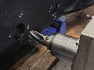
Machining setup shown in Figure 1.
Linear Normal Entry
This is the simplest method, involving initial linear entry followed by circular milling in successive layers. It features the shortest tool path, as illustrated in Figure 2. This approach is suitable for workpieces with minimal surface allowance.
However, when machining workpieces with significant allowance, the depth of linear entry increases, leading to greater cutting depth and progressively higher cutting resistance. The abrupt change in cutting direction when transitioning from linear to circular milling can easily cause insert breakage and damage to the tool end cap.
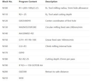
To mitigate insert damage and reduce machine load, the feed rate for linear entry is set to 40% of the normal feed rate. The CNC program for linear normal entry is detailed in Table 1.
Circular Tangential Entry
In CNC machining, circular tangential entry is a widely used method. Compared to traditional linear entry, it offers:
Distributed cutting forces→ Higher tool life
Reduced machine load→ Improved machining efficiency
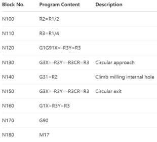
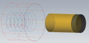
As shown in Figure 3, the tool transitions smoothly into circular milling via a tangential arc, ensuring stable cutting. However, this method requires:
- Calculation of entry base points and tangential arc radii
- Additional program blocks (solved by creating a fixed subroutine L01called by the main program)
(3) Helical Entry
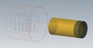
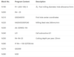
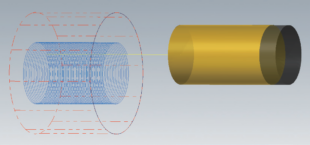
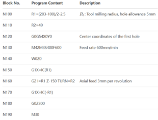
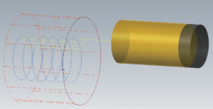
Helical milling is a well-established hole-making process. The tool performs simultaneous circular milling and axial feed, forming a spiral tool path as shown in Figure 4. This method provides uniform cutting force distribution, effectively reducing vibration and tool wear while significantly improving machining stability and hole accuracy.
The helical milling process offers simple and flexible operation, allowing real-time adjustment of cutting parameters according to processing requirements, making it suitable for efficiently machining holes of different diameters. The helical entry CNC program is detailed in Table 4.
(4) Plunge Milling Entry
Plunge milling involves a rotating tool directly cutting into the workpiece along the Z-axis direction, then retracting along the Z-axis. The tool subsequently shifts a certain distance in the X or Y-axis direction before performing another axial cut .
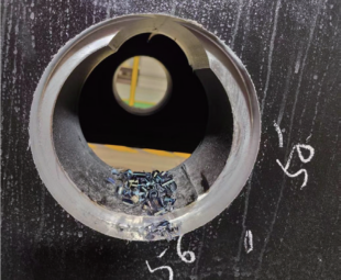
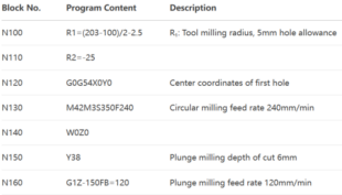
In this specific machining process, plunge milling is first used to remove excess material along the entry path, creating a starter hole. This is followed by circular layer-by-layer milling. The tool path is illustrated in Figure 5, with the entry positions shown in Figure 6.
Compared to traditional milling methods, plunge milling can increase metal removal rates by up to 50%. While specialized plunge milling tools exist, practical machining has demonstrated that corn cob cutters can effectively perform plunge milling as long as the cutting depth per pass does not exceed the insert width. This application marks the first successful implementation of corn cob cutters for plunge milling operations. The corresponding CNC program is detailed in Table 5.
Comparison of Four Entry Methods
The four methods were tested continuously for machining sprocket wheel holes on track frames, with results shown in Table 6.
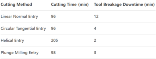
Key Findings from Table 6:
Linear Normal Entry had the longest tool breakage downtime.
Unidirectional cutting increases radial cutting depth, raising resistance and causing spindle vibration and insert chipping.
Requires multiple passes, reduced feed rates, and shallower cuts, leading to longer total machining time.
Circular Tangential Entry showed lower cutting resistance and fewer insert breakages due to two-axis simultaneous entry.
However, programming complexity increased.
Helical Entry had the lowest insert breakage rate and minimal machine load.
Disadvantage: Longest total machining time due to small axial pitch and extended tool paths.
Plunge Milling provided stable cutting with low resistance and relatively few insert failures.
Ideal for deep-wall hole machining.
Summary Rankings:
① Machining Time: Helical > Linear > Circular > Plunge
② Insert Breakage: Linear > Circular > Plunge > Helical
③ Machine Power: Linear > Circular > Plunge > Helical
For optimal efficiency and tool cost, circular tangential and plunge milling are preferred. Plunge milling, with its simple tool paths and programming, is especially suitable for beginners.
S? k?t lu?n
Each entry method has distinct advantages and should be selected based on workpiece material, tool type, and machine capability.
Key Discovery:
Corn cob cutters can perform axial plunge milling, making them highly effective for rough machining deep holes (e.g., excavator buckets and lifting beams).
This innovation boosts productivity and shortens production cycles, proving worthy of wider adoption.


