Fracture Process
The fracture and separation of materials during metal cutting constitute a complex dynamic process involving multiple physical mechanisms. Research indicates that this process primarily consists of three key stages:
Plastic deformation occurs first. Crack initiation and propagation follow. Finally, material separation is achieved.
Based on extensive experimental data and theoretical analysis, this phenomenon can be systematically explained as follows:

Fracture Types and Mechanisms
According to material response and processing conditions, fracture can be divided into the following categories:
Shear fracture
Dominant type, where shear bands form at the tool-workpiece contact surface, and material separates along slip planes. For example, pure shear fracture is common in highly plastic materials (such as low-carbon steel), with fracture surfaces appearing wedge-shaped; microvoid coalescence fracture achieves separation through microvoid nucleation and aggregation.
Tensile fracture
At the tool’s leading edge or chip’s free surface, material forms tear ridges due to tensile stress, mostly occurring in brittle materials or under high cutting speed conditions.
Cleavage fracture
Under low temperature or impact loading, cracks rapidly propagate along specific crystal planes (cleavage planes), producing flat and shiny fracture surfaces, commonly seen in body-centered cubic metals (such as ferritic steel).
Basic Stages of Fracture
The fracture in metal cutting can be divided into three stages:
Crack initiation: When the tool contacts the workpiece, localized stress concentration leads to the formation of microcracks inside or on the surface of the material. For example, in the first deformation zone (chip formation zone) during cutting, the material undergoes slip deformation due to shear stress, thereby initiating cracks.

Crack propagation
As the tool advances, the crack extends along specific paths. The propagation direction is influenced by stress state and material properties, potentially manifesting as shear fracture (along the direction of maximum shear stress) or tensile fracture (along the direction of maximum normal stress).
Final separation
The crack penetrates through the material to form chips, and the resulting fracture surface may exhibit either ductile (fibrous) or brittle (crystalline) characteristics.
Dynamic Fracture in Cutting Process
Stage Division
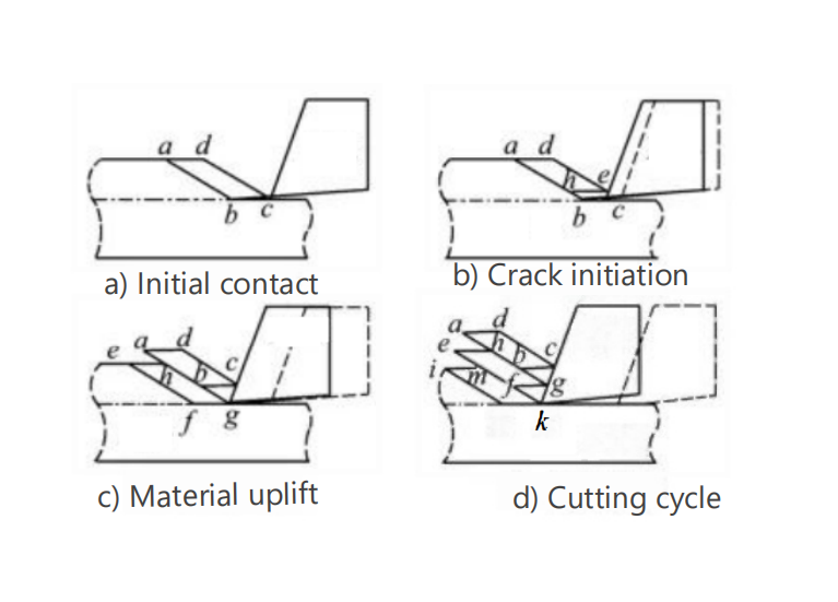
Taking the cutting card theory illustrated in the following diagram as an example, the cutting process is divided into four stages: initial contact, crack initiation, material uplift, and cyclic phase. The crack initiation stage represents the critical point for fracture formation, while the cyclic phase involves periodic crack nucleation, resulting in saw-tooth shaped chips.
Deformation Zone Effects
Primary Deformation Zone (A-H region): Material undergoes intense shear deformation, forming initial cracks.
Secondary Deformation Zone (G-E region): Friction between chip and tool causes additional plastic deformation, potentially accompanied by localized fracture.
Tertiary Deformation Zone (E-D region): Workpiece surface material fractures due to tool flank face compression, forming the machined surface.
Key Influencing Factors
Tool Parameters: The tool’s rake angle, clearance angle, and major cutting edge angle affect stress distribution. For example, increasing the major cutting edge angle reduces cutting forces but may alter crack propagation paths.
Cutting Speed
Low speed → Ductile fracture; High speed → Brittle fracture (thermal softening effect reduces material strength).
Feed Rate
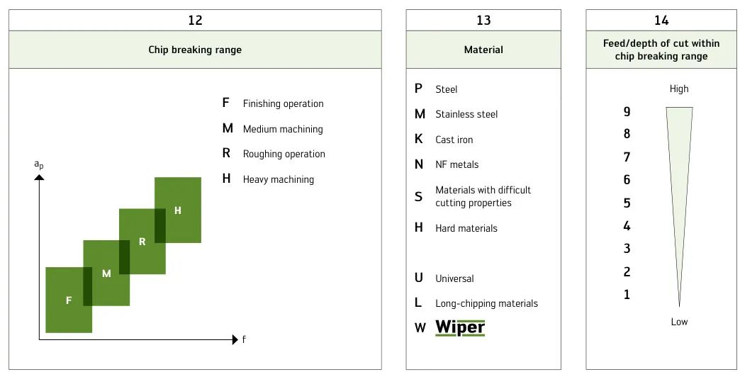
Large feed increases cutting thickness, promoting fracture (as utilized in chip breaker design).
Tool Rake Angle
Negative rake angle increases compressive stress, suppressing fracture; Positive rake angle intensifies tensile stress.
Edge Roundness Radius
Dull cutting edges enhance extrusion, easily inducing microcracks in brittle materials.
Clearance Setting
In shearing operations, the clearance between upper and lower blades (typically 5-10% of material thickness) controls crack meeting position. Improper clearance leads to increased burrs or rough fracture surfaces.
Material Properties
High ductility materials (e.g., aluminum) tend toward ductile fracture, forming fibrous fracture surfaces; Brittle materials (e.g., cast iron) readily exhibit cleavage or intergranular fracture.
Usinagem Conditions
High-speed cutting may induce adiabatic shear bands, causing periodic cracks and saw-toothed chips; Low temperature or alternating loads promote brittle fracture.
Material Characteristics
| material type | fracture tendency | Reason |
| low carbon steel | baixo | High plasticity, easy to form continuous chips |
| gray pig iron | Alto | Graphite sheets weaken the matrix and promote cracking |
| Liga de titanio | médio | The local shear band leads to adiabatic shear fracture |
Performance in Actual Metal Cuttings
Chip morphology: Continuous cutting produces ribbon-like chips, while periodic fracture leads to saw-toothed chips.
Surface quality: Incomplete fracture generates burrs, whose height is positively correlated with clearance and material ductility. For example, excessive clearance significantly increases burr height.
Energy consumption: The fracture process requires overcoming material shear strength and plastic deformation energy; optimizing tool angles can reduce energy consumption.
Typical Case Analysis
Case 1: Crumbling Control in Cast Iron Cylinder Metal Cutting
Problem: Edge chipping occurs when cutting gray cast iron, and surface roughness exceeds standards.
Solution:
Switch to CBN tools (high hardness reduces compressive stress);
Use small feed rate (f = 0.1 mm/rev) and negative rake angle (?5°).
Case 2: Adiabatic Shear Fracture in Titanium Alloy Aerospace Components
Problem: Localized melting and adhesion of chips to the tool during cutting.
Solution:
High-pressure coolant to suppress temperature rise;
Optimize cutting speed to vc = 50 m/min.
Sumário
Fracture in metal cutting results from the combined effects of mechanical response and metal cutting parameters. By controlling tool design (e.g., rake angle, clearance), optimizing cutting parameters (e.g., speed, feed rate), and considering material properties (e.g., ductility, fracture toughness), efficient and low-damage material separation can be achieved. Understanding fracture mechanisms is crucial for improving metal cutting quality, reducing burrs, and extending tool life.


