The so-called U-axis refers to the processing method that can only be completed by lathe in the past and can also be completed by machining center. While the spindle rotates, the tool can be numerically controlled along the radial direction. Therefore, the surface and spherical surface can be machined with good accuracy. Because the lathe processing can also be completed with the machining center, the machining process is also intensive.
These two videos show two major features of U-axis machining:
1. One knife can be used for multiple purposes;
2. Radial movement on the machining center, with turning function.
The U-axis cutter used for complex workpiece processing on the machining center is composed of:
Fig. 1 Schematic diagram of U-axis tool transmission
What is the U-axis?
While the cutter rotates, the cutter head can move radially along the end face of the tool holder. This kind of axis that can reach the accuracy of 0.001mm and move along the radial direction under the control of NC is called U-axis.
Figure 2
What kind of workpiece can the U-axis tool process?
Turning parts that can be processed by machining center (outer circle processing, inner hole processing, end face processing) and U-axis tools can be processed; It can also realize conical surface processing, radial processing, thread processing, groove processing and so on

Figure 3
What is the maximum diameter of the U-axis tool?
The maximum travel of U-axis tool is fixed, but the size range of Machinable workpiece can be expanded by changing the tool holder. The tool holder can be designed arbitrarily as required. For example, the bore diameter of the boring tool can be changed, and the installation position of the tool head can deviate from the center.Figure 4 tool travel calculation
Can external surface turning be realized by U-axis tool?
The turning of the outer surface of the workpiece can be realized by adjusting the installation direction of the cutter head, that is, turning the cutter head back to the inner installation.
Figure 5 external surface turning
Can U-axis tools be used for re cutting and boring?
Yes, as shown in the figure: (machine feed: TVU4 (BT40), material: fc25 (v = 80m / min), cutting depth: 6mm, feed: 0.2mm/rev, material: S45C (v = 120m / min), cutting depth: 4mm, feed: 0.1mm/rev)
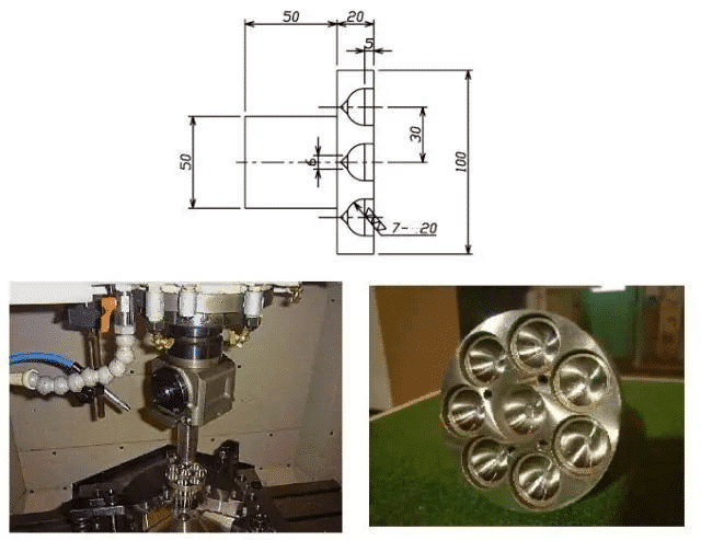
Figure 6 cutting and boring
What precision can be achieved by machining U-axis tools?
By using a set of automatic measurement and compensation system, the tolerance requirements of machining can be ensured to achieve the positioning accuracy repetition of ± 3 μ m. Positioning accuracy ± 1.5 μ m
How much roundness can the U-axis cutter achieve?
The case shown in the above figure: the roundness of the straight cylinder is 2.3 μ m. Cone roundness 2.6 μ M (processing conditions: rotating speed 1000rpm, feed: 0.06mm/rev)Figure 7 roundness machining
Up to now, we know that for complex workpieces, the traditional practice is to process each face, hole and column with a separate tool. The machining center with U-axis cutter can carry out all kinds of machining as long as the complex workpiece is fixed on the workpiece table, and the accuracy is also guaranteed. The specific performance is as follows:
1. The number of boring turning tools can be reduced. One U-axis tool is equivalent to several boring tools
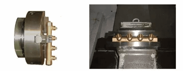
Figure 8
2. It is easy to adjust and is used for machining workpieces with complex shapes. For complex workpieces, the traditional method is to turn and add after counterweight. Now using the machining center with U-axis cutter, the workpieces can be fixed on the workbench for machining.
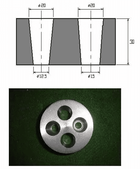
Figure 9
3. Unless the U-axis cutter is used, the machining center cannot process the inner cone. See the processing case below (material: S45C size: φ sixty × 30 processing conditions spindle speed: 2300rpm feed: 0.06mm/rev processing accuracy surface roughness: 4S)
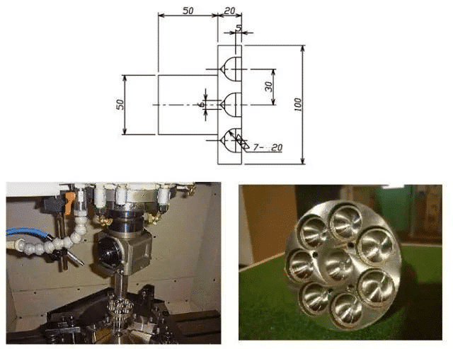
Figure 10 machining of inner conical surface
4. Unless the U-axis cutter is used, the machining center cannot process the spherical surface. As shown in the following figure (material: scm414 hardness: hrc58 ~ 62 processing conditions spindle speed: 600rpm feed: 0.05mm/rev feed) φ 0.1mm machining accuracy shape φ 200.0278 + 0.033 (surface roughness: 2.5s)Figure 11 spherical surface machining
5. Finally, the program of U-axis tool is also very simple. The format (radius instruction) is the same as that of lathe program. Using G01 and G02, the taper R can be processed freely.
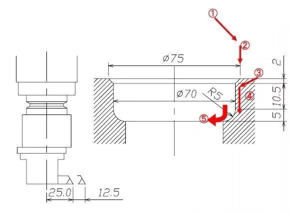
Figure 12 processing drawing
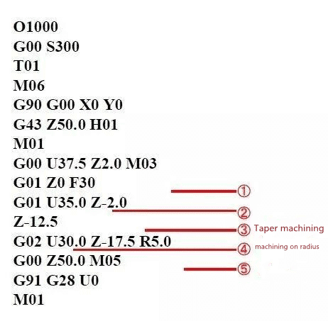
Figure 13 preparation procedure

