CNC Machine Bed
CNC Machine Bed Structure
The bed refers to the basic part used to support and connect several components, equipped with guide rails. The bed is one of the key basic components of the machine tool, requiring sufficient dynamic and static stiffness and accuracy retention. In order to reduce connection links, increase the quality of supporting components, and improve the rigidity of the bed, it is usually designed as an integral part with a stable cross-sectional form. Figure 1?shows the bed of a horizontal machining center, which is a T-shaped integral bed with good rigidity and accuracy retention, but its processing is relatively difficult. Figure 2?shows the bed of a vertical machining center, which connects the bed with the base supporting column to form an integral bed. This type of bed has good processing technology, rigidity, and accuracy retention.
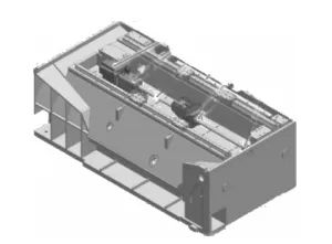
Figure 1 Horizontal Machining Center Bed

Figure 2 Vertical Machining Center Bed
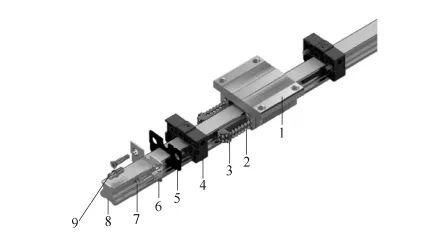
Diagram3: Typical Structure of Rolling Guide Rail
1—Slider 2—Ball 3—Frame 4—Guide 5—Seal Plate 6—End Plate 7—Hexagon Bolt 8—Lubrication Nozzle 9—Guide Rail
The slider 1 is connected to the slide by bolts and can perform reciprocating linear motion along the guide rail 9. The ball 2 and the frame 3 ensure the motion of the slider, and the guide 4, also known as the reverse, achieves the ball reversal when the slider changes direction. The seal plate 5 is a very important component that can effectively prevent external particles and contaminants from entering the slider and can also act as a scraper. The lubrication nozzle 8 can be connected to the oil nozzle for regular manual lubrication. Many high-precision machining centers use a central lubrication system with higher costs, which can automatically lubricate the inside of the slider through the lubrication nozzle regularly to ensure the system’s life and performance.
CNC Machine Bed Components
Other bed components include bed guide rails, slide and slide drive motors with ball screws, bearing seats, servo motors, and connection devices between servo motors and ball screws. The connection device usually includes elastic couplings and bearing for supporting the screw.
Bed Guide Rails Consist of the Following Parts:
Przesuwna szyna prowadz?ca. Obrabiarki CNC z przesuwnymi szynami prowadz?cymi zazwyczaj maj? mi?kkie pasy z politetrafluoroetylenu do szyn prowadz?cych (powszechnie znane jako plastikowe p?yty prowadnic) naklejone na szyny prowadz?ce cz??ci ruchomej, aby zapewni? dobr? dok?adno?? ruchu szyn prowadz?cych ?o?a poprzez hartowanie szyn prowadz?cych ?o?a i zastosowanie szlifowania obwodowego . Wspó?czynnik tarcia plastikowego paska prowadnicy jest o oko?o 0,04 wy?szy ni? w przypadku tocznej szyny prowadz?cej, ale mo?e spe?ni? wymagania. Odkszta?cenie mi?kkiego paska jest niewielkie i w ka?dych okoliczno?ciach odkszta?cenie na obrabiarce jest mniejsze ni? 1%. Materia? ten ma dobr? samosmarno??, nawet je?li smarowanie jest niewystarczaj?ce, nie nast?pi spawanie, co czyni go idealnym materia?em na szyn? prowadz?c? do obrabiarek CNC. Wi?kszo?? centrów obróbczych z posuwem <15 m/min zazwyczaj wykorzystuje przesuwne szyny prowadz?ce, podczas gdy te z posuwem > 15 m/min najcz??ciej korzystaj? z prowadnic tocznych.
Rolling guide rail. Small and medium-sized machining centers generally use linear rolling guide rails with overturning resistance. This type of guide rail has low friction resistance (friction coefficient of 0.003~0.004), flexible movement, high accuracy, and is cheap to produce due to specialized production, and easy to install. Figure 2-3 shows the typical structure of a rolling guide rail.
CNC Machine Spindle Components
The spindle is the shaft that drives the workpiece or tool to rotate. Its end is equipped with a tool for cutting, which is a box-shaped power component that can perform cutting. The spindle components consist of the spindle box, spindle motor, spindle, and spindle bearing, etc. The spindle is the power output component of the machining center during cutting. Its startup, stop, speed change, and direction change are all controlled by the numerical control system. Its rotational accuracy and positioning accuracy are important factors affecting the machining accuracy of the machining center.
CNC Machine Numerical Control System
The numerical control system is a control system that uses numerical data. During operation, it continuously introduces numerical data to achieve automatic control of a certain production process. It executes partial or all numerical control functions according to the control program stored in the computer memory and is equipped with a dedicated computer system with interface circuits and servo drive devices. By using digital, text, and symbol composed digital instructions to control the action sequences and processing processes of one or more mechanical devices, it typically controls mechanical quantities such as position, angle, speed, and switch quantities.
The numerical control system of the machining center consists of CNC devices, programmable controllers, servo drive systems, and panel operation systems. It is the control center for executing sequential control actions and processing processes. The CNC device is a position control system. Its control process involves data processing and interpolation calculations based on input information to obtain the required motion trajectory information, which is then output to the execution components to produce the required workpiece.
Automatic Tool Changer System of CNC Machine
The automatic tool changer system refers to a machining device that realizes continuous machining and tool changing requirements between workpiece processes, consisting of a tool magazine and a tool changing device. Among them, the most widely used automatic tool changer systems are three types: turret-type tool changer system, spindle direct tool changer system with disc-type tool magazine, and tool changing system with chain-type tool magazine and mechanical hand. The tool magazine can be vertical or horizontal. When it is necessary to change the tool, the CNC system issues instructions, and the tool is taken from the tool magazine by the mechanical hand and installed into the spindle hole. Then, the tool on the spindle is returned to the tool magazine, completing the entire tool changing process.
Auxiliary Devices
Auxiliary devices include lubrication, cooling, chip removal, protection, hydraulic, pneumatic, and detection systems, etc. Although these devices do not directly participate in cutting motion, they are indispensable parts of the machining center, ensuring the processing efficiency, accuracy, and reliability of the machining center.

