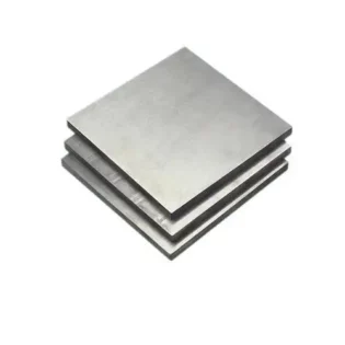
Ceramic Materials for Smartphone Casings
Among all ceramic materials, zirconia (ZrO?) ceramics have emerged as a next-generation smartphone body material following plastics, metals, and glass. Beyond demonstrating high strength, hardness, and chemical stability (resisting acids/alkalis and corrosion), zirconia ceramics additionally provide:
? Superior abrasion and scratch resistance
? Zero signal interference
? Excellent thermal dissipation
? Premium aesthetic quality
Figure 1 illustrates a zirconia ceramic smartphone back panel.

Ceramic feels similar to glass but is much harder (second only to sapphire on the Mohs scale), making ceramic phones more scratch-resistant and durable – an ideal back cover material. Currently mainly used for phone back panels and fingerprint sensor covers. When first applied to phone frames, the new and unperfected process resulted in only 35% yield, leading to low production capacity and high prices. After machining optimization, the yield can be increased to over 80%.
Analysis of the Processing Technology of Ceramic Phone Case Parts
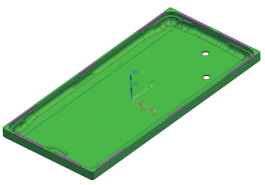
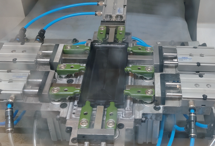
Part drawing and clamping method
The ceramic phone case parts are shown in Figure 2, and the processing and clamping methods of the parts are shown in Figure
The main problems in the production machining
The machining quality stability of components is poor, with frequent defects (see Fig.4). Main issues include significant dimensional deviations and surface flaws such as flow lines, tool marks, scratches, circular tool patterns, uneven textures, and machining vibrations. The defect distribution is shown in Fig.7.
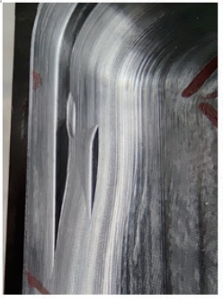
a)Streamlined texture
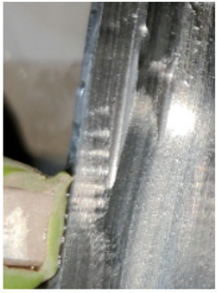
b) Vibration marks
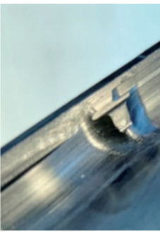
c) Knife connection marks
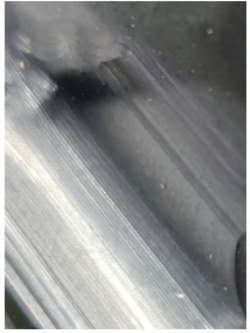
d) Brushing
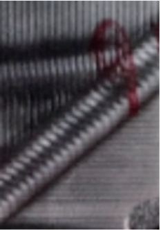
e) Knife ring pattern
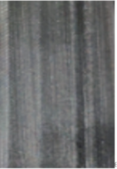
f) Light and shade patterns
Figure 5 Processing defects
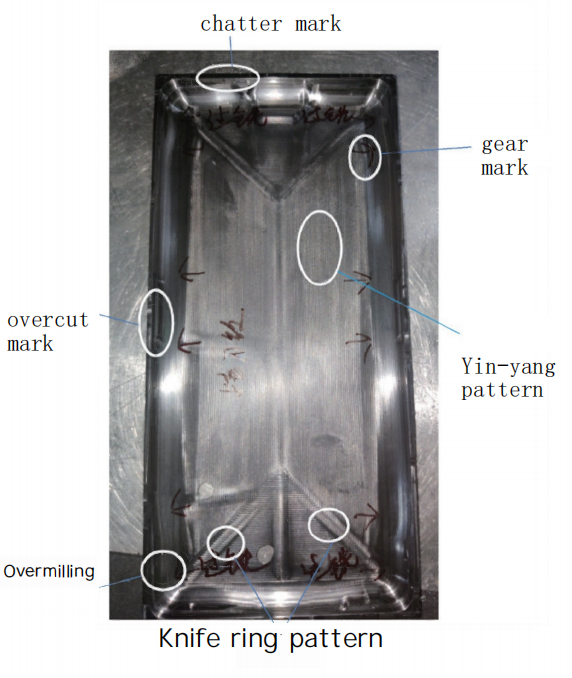
Figure 6 Defect Distribution
Based on actual part processing performance and machining analysis, the following conclusions are drawn:
1.Ceramic is a new material with machining techniques still in exploration, lacking mature reference processes.
2.Its machining characteristics demand higher requirements for equipment, tools, and fixtures.
3.Poor surface quality with defects like dimensional inaccuracies, overcut marks, uneven textures, tool rings, and vibrations.
4.Initial yield rate is extremely low (~35%).
5.Unpredictable grinding tool lifespan due to ceramic firing process, compromising dimensional accuracy.
Key solutions focus on eliminating defects, stabilizing accuracy, improving yield, and reducing rework through comprehensive optimization of equipment, processes, fixtures, and cutting tools.
Influencing factors of machining quality and the process for solving problems
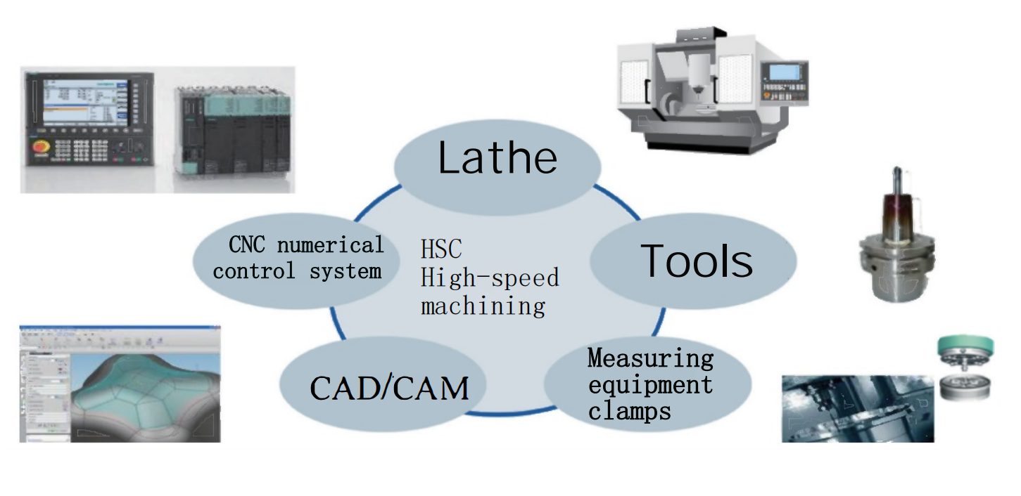
During part machining, numerous factors affect processing quality, including machine tool mechanical accuracy, CNC system parameter matching, program quality, tool selection, and measuring equipment precision. Issues in any of these areas can lead to unstable part quality. The influencing factors are shown in Fig.7.
The machining of solving the problem is shown in Figure 8. Analyze the processing problems one by one according to the flowchart and seek solutions.
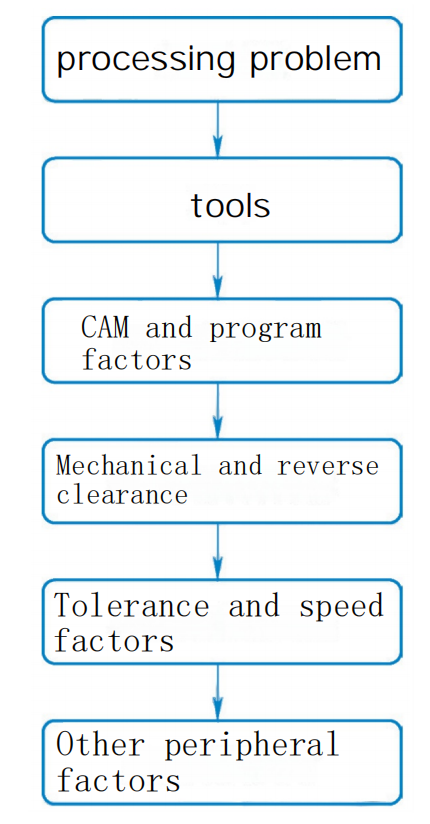
Figure 8 The process of solving the problem
?
The influence of cutting tools on processing
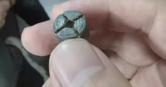
It was found that the cutting tools were severely worn during production. The hardness grade of zirconia ceramics is 9.0. The only material that can be processed is diamond grinding wheels. Different from traditional processing techniques, the wear rate of diamond grinding wheels is relatively fast. The wear of the grinding head is shown in Figure 9.
Tool manufacturing machining
There are currently two grinding head manufacturing processes: sintering and electroplating. The sintering process creates chemical bonds between the matrix metal and diamond particles with high encapsulation, making diamonds less likely to detach, thus offering better wear resistance and longer lifespan. The electroplating process mechanically encapsulates diamond particles with weaker retention than sintering, resulting in inferior wear resistance and lifespan but sharper edges. Additionally, sintering is unsuitable for certain slender and pointed products as it may deform the substrate. The high sintering temperature can also degrade diamond performance. The electroplating process is currently used.
Vibration marks and tool marks analysis
After machining one part using the program, measurements of grinding heads T4 and T5 showed inconsistent wear between the two tools, with a 0.01mm error difference. The tool measurements are shown in Fig.10.
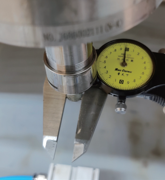
a)Grinding head dimensions before processing
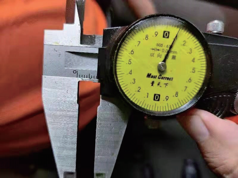
b) Dimensions of the grinding head after processing
Figure 10 Measurement of the cutting tool
Analysis of the machining program revealed that when two tools simultaneously act on the same machining surface with inconsistent wear amounts, the finishing grinding head cannot fully reach the target surface at machining protrusions, resulting in tool mark phenomena on the machined surface.
As shown in Figure 11, the machining paths of grinding heads T4 and T5 differ significantly, leading to substantial variations in their wear amounts. According to process requirements, both tools machining the sidewall must act on the same wall simultaneously. When wear amounts are inconsistent, tool marks will appear on the sidewall (see Figure 12).
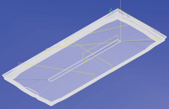
a) Grinding head tool path No. T4
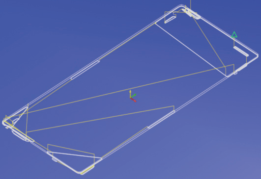
b) T5 grinding head tool path
Figure 11 Program trajectory
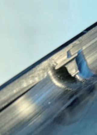
a)Phenomenon of knife marks on the side wall
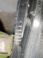
b) Local magnification
Figure 12 Phenomenon of knife marks(3) Measures to Solve Sidewall Vibration Marks and Tool Marks
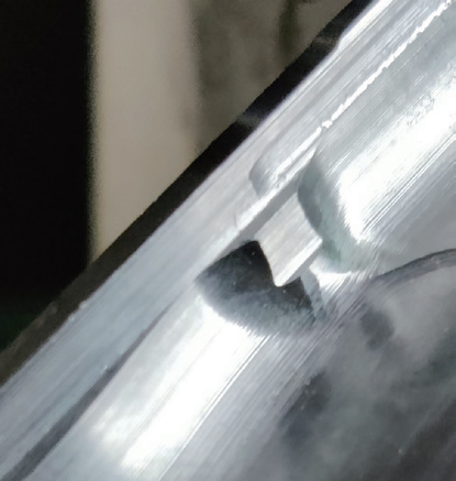
Replace the grinding head manufacturing machining with sintering technology to improve wear resistance. Modify the machining program by using CAM software to position the sidewall program as close as possible to the median tolerance zone, ensuring first-piece success rate. After initial machining, add an in-machine tool measurement procedure to promptly compensate for tool wear and ensure product consistency. A comparison of part surfaces before and after process optimization is shown in Figure 13.
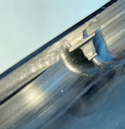
a)Before optimization
b) After optimization
Figure 13 Comparison of the parts’ surfaces before and after process optimization
The influence of programs on processing
The requirements in machining can generally be summarized as high efficiency, high quality, and high precision. These three factors are often difficult to achieve simultaneously and require trade-offs. In actual machining, due to the special application of ceramic phone cases, the smoothness of machined surfaces and dimensional accuracy are particularly critical. On this basis, production efficiency should be improved as much as possible, with program optimization being key to enhancing production quality. According to on-site conditions, machining programs need to be optimized, with the optimization machining shown in Figure 14.
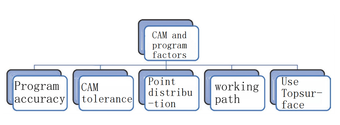
Figure 14 Program optimization process
?Impact of program precision on machining
As shown in Figure 15, the left-side graphic shows simulation results from a CAM-generated program with 4-decimal precision (4 digits after decimal point), demonstrating smoother workpiece surfaces. The right-side graphic, simulated with 3-decimal precision, clearly exhibits streaking patterns on the workpiece surface.
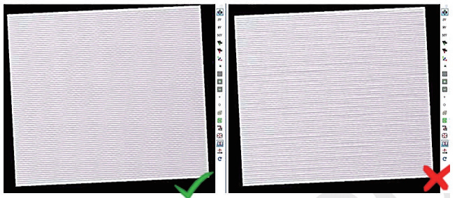
Figure 15 Comparison of program accuracy
?Influence of program tolerance on machined surfaces
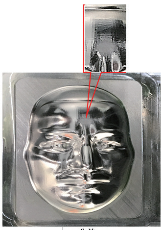
The NC machining program generated by CAM post-processing directly affects surface quality. Different program tolerances produce distinct machining effects on the surface. A comparison of program tolerances is shown in Figure 16.
a)The CAM tolerance is 8μm
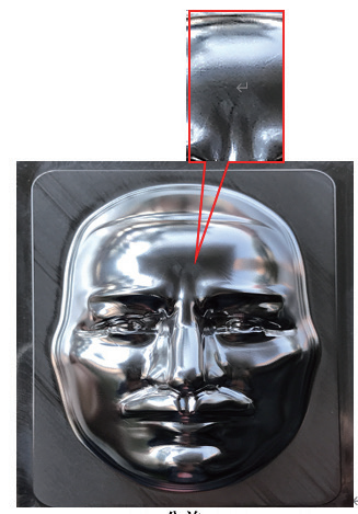
b) The CAM tolerance is 1μm
Figure 16 Comparison of program tolerances
In summary, when generating programs with CAM software, appropriate machining strategies, point stepover, and feed rates should be selected to optimize the point distribution in NC programs. Good point distribution can improve surface quality and reduce machining time. Conversely, poor distribution will degrade surface quality.
Main measures to address flow line issues
The flow line phenomenon is shown in Figure 17. The tool path point distribution in ceramic mold machining directly relates to the sidewall flow line phenomenon.
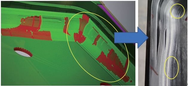
Figure 17 Streamline phenomenon
Optimize the tool path by setting the CAM software point spacing to 0.2mm and program tolerance to 0.006mm. The premium surface optimization function can replace the fine surface optimization function for cutting. The premium surface optimization function will re-optimize unsatisfactory points and tool paths in the program. After optimization, flow line textures completely disappear. A comparison of machining effects before and after program optimization is shown in Figure 19.
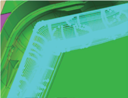
a) Point distribution before program optimization
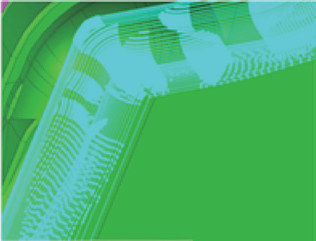
b) Point distribution after program optimization
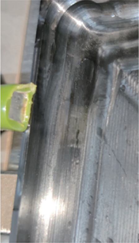
c) Pre-machined surface for point position optimization
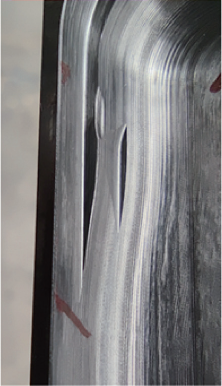
d) The machined surface after point position optimization
Figure 18 Comparison of machining effects before and after program optimization
Tool mark pattern analysis
Tool marks are common machining issues that may appear as regular/irregular rings, gradient rings, single rings or corner rings during linear feed or at corners, resembling Audi’s logo.
These marks occur at tool direction changes with varying spacing. As marks fade with distance, vibrations are identified at reversal points. During reversal, X/Y axis screws accelerate/decelerate, where acceleration settings cause slight overshoot and vibration, creating entry/corner marks.
Solutions for tool marks
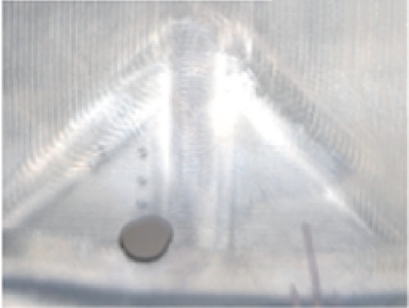
Adjust acceleration parameters to reduce overshoot/vibration. Add “Top surface” command to smooth bad points, reduce impact and eliminate contour errors. Optimize toolpaths with more arcs for smoother turns. Post-optimization comparison (Fig.19) shows near elimination of tool marks.
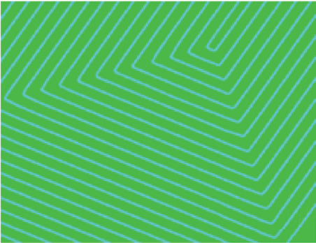
a)Optimize the rake path

b) Optimize the rear cutting path
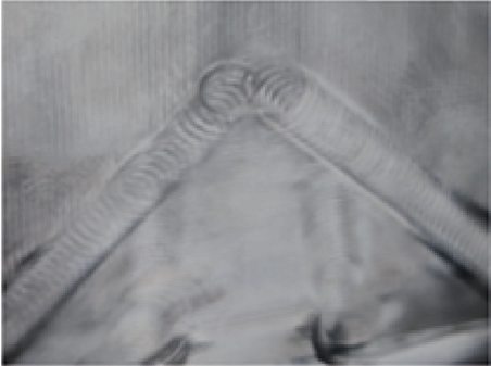
c) Machining surfaces before program optimization
d) The processed surface after program optimization
Figure 19 Comparison of processing effects before and after tool path optimization
The influence of mechanical and system parameters on processing
Influence of mechanical and backlash on machining
The impact of backlash on machining is shown in Figure 20. When machining molds using the same program under identical working conditions, backlash compensation and static friction compensation significantly affect the machined surface.
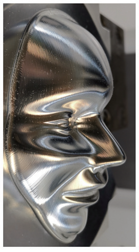
a)The reverse clearance is large before adjustment
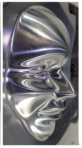
b) The backlash before adjustment is small
Figure 20 The influence of backlash on processing
Impact of speed inconsistency on machining
Cutting tests were conducted to study the effect of system parameters. Different maximum axis jerk values (system parameter MD32431) were tested using the same program while monitoring toolpath speed via system Trace function. Analysis of monitoring data using AMWT software produced the red/yellow/blue curves in Figure 21, where colors indicate speed variations (red=fastest, blue=slowest). Results demonstrate system parameters directly affect machining speed variations.
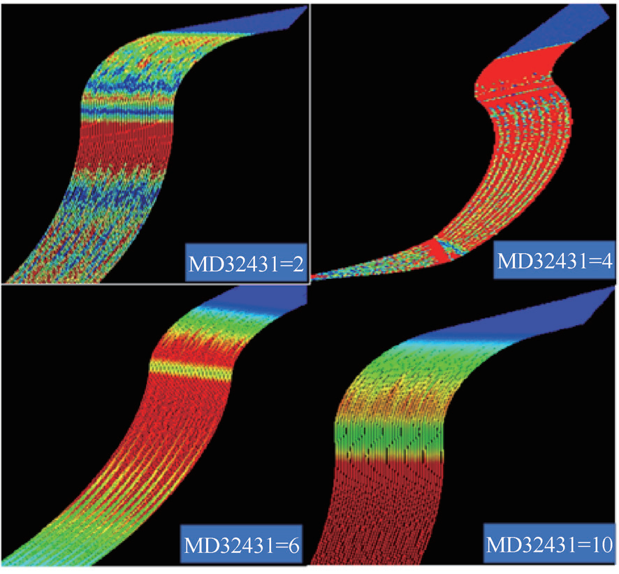
Figure 21 The influence of system parameters on processing speed
The impact of speed optimization on machining is shown in Figure 22. When the toolpath speed is inconsistent, the tool’s varying speed on the machined surface creates uneven textures, known as “streaking phenomenon.” This can be optimized by adjusting system parameters and program tolerances.
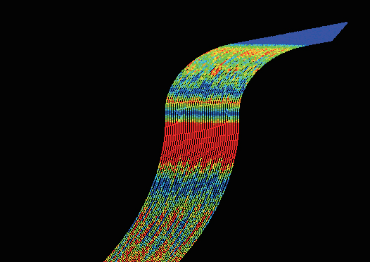
a)Velocity variation before optimization
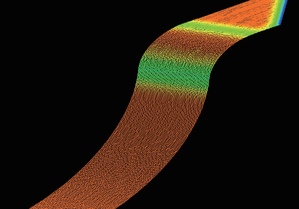
b) Speed variation after optimization
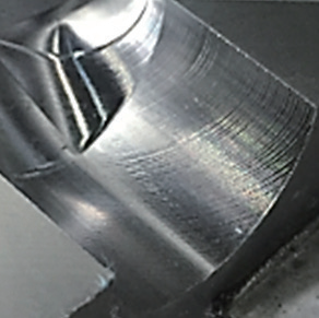
c) Speed optimization of the pre-machined surface
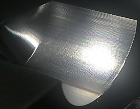
d) The processed surface after speed optimization
Figure 22 The influence of speed optimization on processing before and after
Disable static friction compensation. Precisely measure backlash values (MD32450) using dial indicators or laser interferometers, focusing on the Z-axis. If excessive backlash exists (linear guides should be ≤0.005mm), perform mechanical adjustments like screw pre-tensioning and bearing alignment. If adjustment isn’t possible, set the value to half the actual backlash or disable backlash compensation for test cuts. Optimize path speed and program tolerance while enabling the “Jerktime” system function. Implementing these optimizations effectively eliminates streaking, as shown in the before/after comparison in Figure 23.
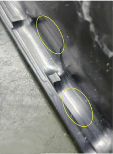
a)The machined surface before parameter optimization
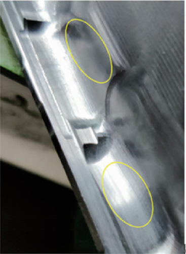
b) The processed surface after parameter optimization
Figure 23 Comparison of processing effects before and after the wire drawing phenomenon is eliminated
??
Through comprehensive optimization of machining equipment, processes, and tools, the processing defects of ceramic materials were overcome. The yield rate of phone casings increased from the original 35% to over 80%, meeting mass production standards and reducing costs. The product has now successfully entered the market.
Ceramic phone casings offer a smooth texture, high hardness, scratch and drop resistance, and zero signal interference. As production techniques mature, ceramic casings are expected to gain widespread consumer preference.


