We found that after approximately 80 hours of operation, there were numerous cracks on sealing rings’surface. Continuing to use it could lead to seal failure and result in significant economic losses. Therefore, it is necessary to conduct damage analysis and safety assessment to address this issue.
Test Materials and Methods
Test Materials
The test specimens were taken from the WC-Ni carbidesealing ring, designated as YWN8. The inner diameter of the sealing ring is 277 mm, the outer diameter is 302 mm, and the thickness is 20 mm, as shown in Figure 1. The primary material of the sealing ring is WC-Ni carbide, with a WC mass fraction of 89% and a Ni mass fraction of 11%. The mechanical properties of the WC-Ni carbide?are presented in Table 1.


Test method
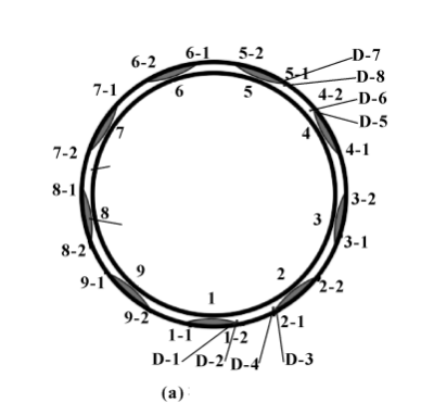
Figure 1(a) depicts a solid view of the damaged sealing ring, which features 9 sets of groove weirs/barricades structures. As indicated by the labels 1 to 9 in Figure 1(b), the test is organized based on the distribution of groove weir areas in the sealing ring, dividing them into 9 groups. Further, these 9 groups are subdivided into 18 smaller regions. Upon magnified observation using a microscope, it was observed that 6 of these regions exhibited surface cracks: namely, 2-2, 3-2, 4-2, 5-2, 6-2, and 7-2, whereas the remaining regions showed no cracks on their surfaces.
For analysis, the test selected the areas of the damaged sealing ring where cracks appeared on the sealing surface. Subsequent steps involved surface residual stress testing, microscopic analysis of the damaged sealing ring’s microstructure, and identifying the reasons behind the appearance of cracks on the sealing ring’s surface.
Results and Analysis
Microscopic Analysis of the Damaged Area
Based on microscopic observations, the 6-2 damaged region exhibited the highest number of cracks. As shown in Figure 2, the SEM morphology of the 6-2 damaged region specimen reveals that there are a total of 5 cracks in the damaged zone. The origins of these cracks are at the junction between the groove weir and the barricade of the sealing ring. Each crack exhibits a trend of expansion along its length.

Analysis Using White Light Interferometer
Based on the SEM analysis mentioned above, it was found that although the crack volume was significant, the cracking depth was relatively shallow. To further investigate the damage characteristics during the sealing ring’s service, white light interferometry (Bruker Contour GT 3D white light interferometer) testing and analysis were performed on the damaged area of the sealing ring.
Figures 3 and 4 respectively depict the three-dimensional morphology at the location of the largest crack and the two-dimensional profile of the deepest point of the crack in the 6-2 damaged region. The results reveal that the roughness of the groove weir area is approximately 0.672 μm, the roughness of the barricade area is about 0.294 μm, and the height difference between the groove weir area and the barricade area is approximately 2.43 μm. The maximum width of the crack is around 126.4 μm, with a maximum length of about 2.75 mm. During testing, the maximum depth of the crack was found to be around 58.84 μm, while the depths of other crack regions were relatively smaller.

Chemical Composition Analysis of the Damaged Area
Energy-Dispersive X-ray Spectroscopy (EDS) Analysis
Based on the microscopic morphology analysis of the mentioned cracks, energy-dispersive X-ray spectroscopy (EDS) was used to analyze the chemical composition of points A, B, and C (corresponding to the specimen matrix, crack area, and the boundary strip between the groove weir and the barricade) as indicated in Figure 2. This was done to determine whether there had been any changes in material composition. The results are shown in Figures 5 to 7.
It can be observed that the specimen matrix primarily contains C, O, Ni, and W. In the crack area, in addition to the aforementioned four main elements, there are also impurity elements such as Cu, Fe, and Ti. This suggests that element transitions occurred in the sealing ring’s mating parts during service, resulting in impurity elements on its surface. The oxygen content in the crack area is significantly higher than that in the matrix, indicating the presence of oxides within the crack area and the occurrence of oxidative wear. Similarly, at the boundary strip between the groove weir and the barricade, in addition to the four main matrix elements, there are trace amounts of impurity elements such as Ti, Fe, and Zr. The damage situation here is similar to the crack area, with the presence of oxidative wear phenomena.


Electron Probe Microanalysis (EPMA) Analysis
To further investigate the extent of damage to the sealing ring and the characteristics of the cracked area, and to analyze the distribution of chemical composition in the damaged area of the sealing ring, electron probe microanalysis (EPMA) was employed to perform surface analysis on the cracked area within the box shown in Figure 8. Based on the EDS analysis results mentioned above, it was established that oxidative wear occurred during the service of the sealing ring. Therefore, four elements—C, W, Ni, and O—were selected for EPMA surface analysis of the test specimen.
Figure 9 presents the EPMA surface analysis results of the specimen. It can be observed that within the cracked area, there is a relatively higher distribution of C and O compared to the matrix, while the distribution of W within the cracked area is relatively lower compared to the matrix. On the other hand, the distribution of Ni within the cracked area does not exhibit significant differences compared to the matrix. It can be inferred that there is a mild level of oxidation within the cracked area, with the primary oxidation product being oxide of W.


Surface Residual Stress Analysis
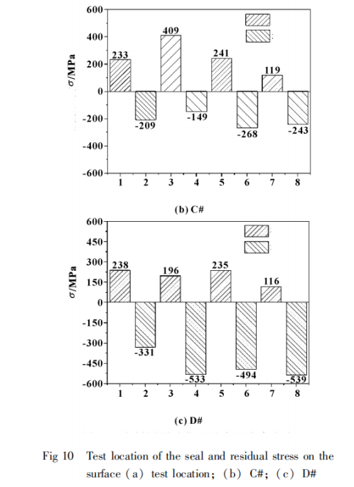
To investigate the surface stress distribution of the sealing ring after service, a portable X-ray residual stress tester was used to conduct residual stress testing on the entire end face of both an unused C# sealing ring and a D# sealing ring (with cracks on the surface) that had been in service for 80 hours. The test positions and their results are shown in Figure 10. It can be observed that unevenly distributed surface residual stress can lead to cracks in the sealing ring. During service, residual stress is released due to friction, resulting in crack formation and failure of the sealing ring.
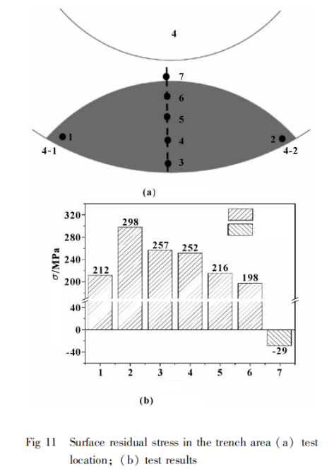
As shown in Figure 11, the residual stress gradually decreases along the radial direction of the sealing ring from the outer ring to the inner ring, transitioning directly into compressive stress in the barricade area. The stress value at the end of the groove weir area is higher than at the beginning (counter-clockwise along the sealing ring). Observed cracks are all located at the end of the groove weir area, indicating that the stress difference between the beginning and end of this area is relatively low compared to the stress difference between the arc ends. This difference in stress is insufficient to cause damage to the sealing ring.


結(jié)論
(1) The majority of crack sources are located at the junction between the groove weir and the barricade of the sealing ring. Most cracks are distributed in the barricade area, where the extent of damage is greater compared to the groove weir area.
(2) Oxidative wear occurred in the damaged area of the sealing ring during service, primarily resulting in oxide products of tungsten (W). The oxidation is relatively mild.
(3) Due to a significant stress difference between the groove weir and the barricade areas of the sealing ring, material damage is prone to occur during service, leading to the initiation of microscopic cracks.
(4) The cracks are relatively shallow, and the damage to the sealing ring is minor. This will not have an immediate impact on operational safety within the short term.


