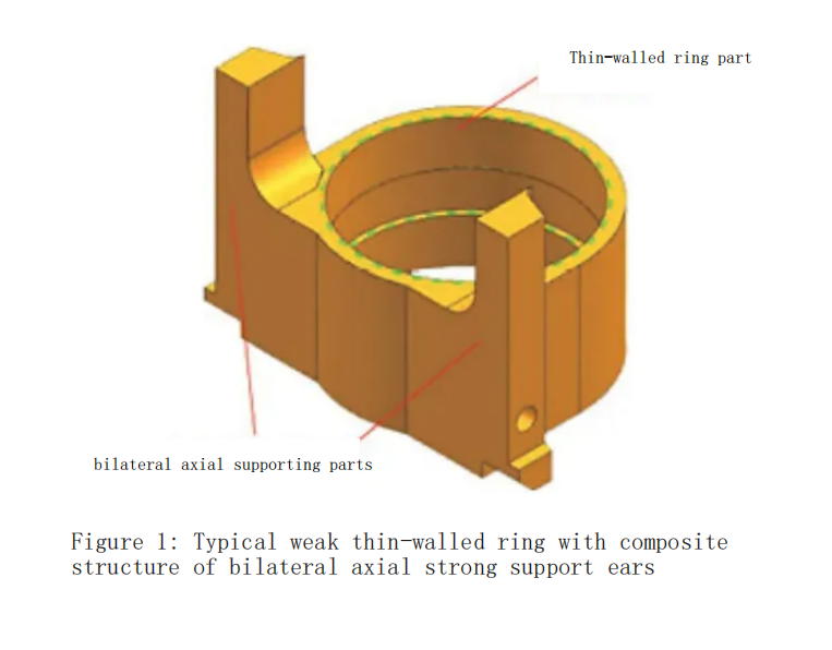
The main body of the part is a weak stiffness structure, which is prone to instability during mechanical machining, especially when machining the outer wall of the ring and clamping the thin-walled ring.
Machining Analysis
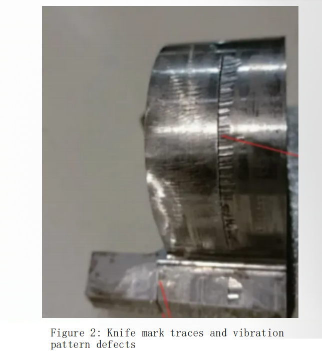
The morphology of the typical weak thin-walled ring with a composite structure of bilateral axial supporting parts after machining with general mechanical machining techniques is shown in Figure 2. The following deficiencies are observed:
(1)Obvious tool marks in the middle of the bilateral axial supporting parts. The upper and lower parts of the bilateral axial supporting parts are formed during two separate machining steps: milling the shape of the thin-walled ring and milling the shape of the bilateral axial supporting parts. Due to the non-coincidence of the process benchmarks between the two steps, obvious tool marks appear in the middle of the bilateral axial supporting parts.
(2)Prominent vibration marks in the middle of the thin-walled ring shape. The wall thickness of the middle part of the ring body is 2mm, which results in significantly insufficient stiffness. During the machining of the thin-walled ring shape, the middle part is prone to instability, leading to the formation of obvious vibration marks. The superposition of these issues collectively results in the machining instability problem becoming a production bottleneck.
Process Optimization
To address the deficiencies of general mechanical machining techniques, a series of compound machining measures have been adopted, including the conversion control of process benchmarks to “bore-face-contour,” the gradual reduction of workpiece stiffness during machining, the reinforcement of stiffness combined with damping and vibration absorption, and the maximization of clamping area and stiffness. These measures aim to achieve stable machining of the weak thin-walled ring with the composite structure of bilateral axial supporting parts.
Precision Conversion of Process Benchmarks
(1) After rough machining the inner shape and end face, precision turn the inner circle and end face to form the process benchmark “bore-face.”
(2) The specific steps for milling the contour positioning benchmark are as follows.
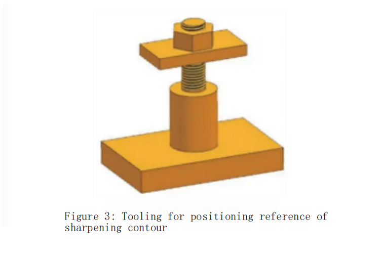
1)Clamp the fixture in the vise (see Figure 3). The bottom surface of the fixture is aligned with the workpiece end face, and the cylindrical surface of the fixture is aligned with the axial direction of the workpiece inner circle. Use a dial indicator to align the fixture bottom surface with a flatness of ≤0.01mm and then secure it.
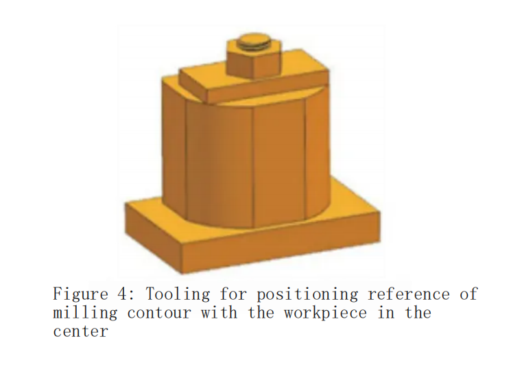
2) Clamp the workpiece on the fixture (see Figure 4). The workpiece end face and inner bore are tightly against the fixture’s positioning surface and are clamped with a pressure plate.
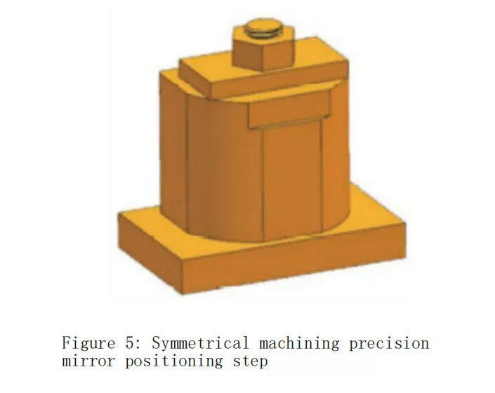
3)Symmetrically machine two identical precision milling positioning steps on the workpiece contour (see Figure 5). The step height is 20mm, which converts the process benchmark from “bore-face” to “contour.”
Steady-state Machining Control
(1) The specific steps for milling the thin-walled ring contour are as follows.
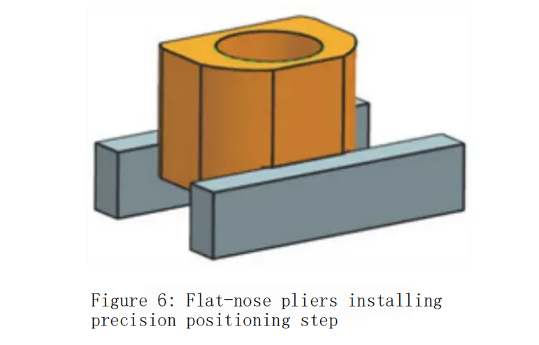
1)Clamp the workpiece with a vice on the precision milling positioning step (see Figure 6).
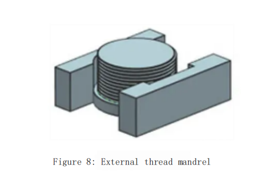
2) Embed polytetrafluoroethylene or nylon washers into the internal thread relief groove of the workpiece, and then use an external thread mandrel to screw into the internal thread of the workpiece to enhance the stiffness of the annular body cavity.
3) Machine the round corners of the bilateral supporting parts and the shape of the thin-walled ring (see Figure 7).

(2) The specific steps for milling the shape of the bilateral axial supporting parts are as follows.
Turn the workpiece around, and use an external thread mandrel (see Figure 8) to screw into the internal thread of the workpiece to enhance the stiffness of the annular body cavity.
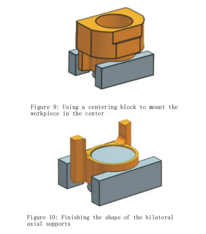
Clamp the workpiece with a clamping block (see Figure 9), and secure it with a flat-nose pliers.
Perform finish machining on the shape of the bilateral axial supporting parts (see Figure 10).
(3) The specific steps for milling the outer step of the bilateral supporting parts?are as follows.
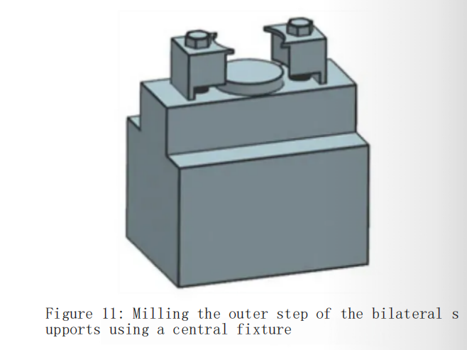
Clamp the fixture with a flat-nose pliers (see Figure 11).
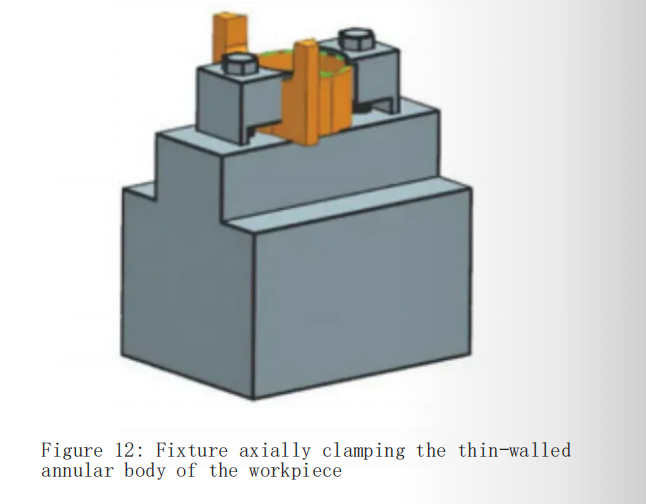
Axially compress the thin-walled ring body of the workpiece with the fixture (see Figure 12).
Press the expanding ring into the inner circle of the workpiece’s thin-walled ring and align the inner circle of the expanding ring with the edge finder.
Machine the structures such as the outer side of the bilateral supporting parts, the step, chamfer, and thread to completion.
Machining Process
According to the optimized process plan, the specific machining process is as follows.
(1) Milling the profile positioning reference: The milling process for the profile positioning reference is shown in Figure 13.
(2) Milling the shape of the thin-walled ring: The shape of the thin-walled ring after milling is shown in Figure 14.
Deja una respuesta
Tu dirección de correo electrónico no será publicada.
